Device for Detecting Glaucoma
Introduction
Go to
This is a diagnostic device to measure the Intraocular Pressure (IOP) of eyeball, a key indicator for glaucoma. This is a degenerative disease characterized by progressive loss of visual field. According to Glaucoma society of India 12 million people are affected by Glaucoma i.e. 12.8 % of total cases of blindness. About half of glaucoma patients go undetected until they lose substantial vision and suffer from irreversible loss of visual function if untreated. The innovative device being developed is expected to help in early detection, screening, and treatment of glaucoma, the leading preventable cause of blindness. The degenerative disease glaucoma is the world’s leading cause of preventable blindness. Glaucoma stems from optic nerve damage due to a buildup of Intraocular Pressure (IOP) in the eyeball. Normal IOP ranges between 10-21mm Hg. After 23mm Hg, the risk of glaucoma increases by 10% for every additional 1mm Hg pressure. Higher pressure damages the neuronal tissue in the optic nerve head (lamina cribrosa). Current treatment involves reducing the pressure to slow the progression of the disease. This requires accurate methods to measure IOP [1].
Definition of Problem
The intraocular pressure is a fundamental parameter of ocular health and disease, with major importance in the diagnosis and management of glaucomatous conditions. The most common cause of chronically elevated IOP is a decrease of trabecular outflow. If this state persists, glaucomatous condition may be developed (Figure 1). Unfortunately, nearly 50% of people with glaucoma may go undetected until they have lost substantial vision. Glaucoma stems from optic nerve damage due to a buildup of Intraocular Pressure (IOP) in the eyeball. Normal IOP ranges between 10- 21mm Hg. After 23mm Hg, the risk of glaucoma increases by 10% for every additional 1mm Hg pressure. Higher pressure damages the neuronal tissue in the optic nerve head (lamina cribrosa), (Figure 2). Current treatment involves reducing the pressure to slow the progression of the disease. This requires accurate methods to measure IOP. The innovative device being developed is expected to help in early detection, screening, and treatment of glaucoma, the leading preventable cause of blindness [2].
Figure 1: (a) Normal vision and (b) vision of a person with glaucoma.

Figure 2:Development of glaucoma.

Development of Device
People residing in rural and remote areas (worldwide) have substantially worse outcome in early detection and diagnosis of glaucoma than those living in metropolitan areas. This gap can be reduced by improved glaucoma prevention activities in primary care, but there is little empirical evidence regarding use of tonometry in rural settings, or the expertise associated with quality of eye care. The people become aware they have glaucoma only after they exhibit symptoms of irreversible damage. The disease is not yet fully understood, however elevations in Intraocular Pressure (IOP) have been identified as a major risk factor. To check their IOP, patients must go to the clinic to see their ophthalmologist. Recent studies show that IOP varies widely throughout the day and thus two to four measurements obtained periodically during the year are not indicative of a patient’s actual IOP. Thus, there is a dire need for a cost-effective intraocular measurement device for early detection and management of glaucoma. The following project was an undertaking to design such a device for patients at risk for glaucoma. Research into the Literature and previous designs led to electromechanical, chemical, and optical solutions [3].
Development Plan
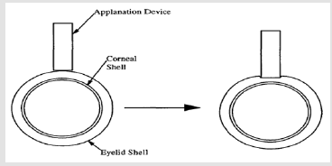
To detect the Patient’s early stage of Glaucoma with comfort it has been decided to account patient’s IOP through eyelid. To measure the IOP we proposed applanation and indentation principles both. The cornea and the eyelid are idealized as two concentric, spherical shells (Figure 3). The applanation device has an area Aa, and force is applied perpendicular to the shells, a critical criteria for achieving accurate IOP when using the equation below. As the force flattens the eyelid, the probe’s applanation area Aa equals the flattened eyelid’s internal area Ae. When the force increases the cornea will also be flattened and its internal area Ac will equal to Ae and Aa. Once the eyelid is flattened, the additional force needed to flatten the cornea will not affect Ae. As a result, the above conditions should satisfy the inequality Aa ≥ Ae ≥Ac.
Figure 3:Model of eyelid and cornea.

Working of Device
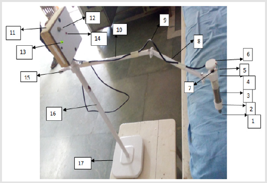
Figure 4 shows a device for detecting glaucoma. As shown in Figure 1 the contact plunger is provided with constant flat area (1). This tip of the plunger (1) is allowed to make the contact with the eyelid another end of the plunger is connected to the piston which enclose inside the main cylinder. The piston gets displaced inside the main cylinder (3). The piston attached to plunger rod is in mesh with upper piston attached to rotating knob (6). In between the bottom and top pistons, the pressure sensor is provided to measure the applanation force. The main cylinder carries a vertical slot to permit the movement of key way. This restricts the rotary motion of piston attached to rotating knob (6). As shown in figure the top surface of piston is connected to circular knob (6) through threaded bolt (7), this arrangement will facilitate for providing constant indentation depth. The upper cap shown in figure comprises a small link, which is used to fix the device on stand shown in Figure 1. The small link is connected to the primary link (8) through link (10). The link (10) is fixed on circular rod (16) through a rotating knob (15). The knob (15) allows the vertical movement of the link (10) in rod (16) to adjust the height of the device in order to make a contact with patient’s eye. Also link (8) and (10) provides all necessary and sufficient movements to the device. The vertical rod (16) is fixed on base (17) and on the top of the rod (16) control unit (11) is fixed. On the panel of control unit (11) a switch (12) is provided, as we put on the switch (12) the green indicator (13) provided on control unit (11) will glow. In normal working the tip (1) makes the contact with closed eyelid and the required indentation is provided by rotating the knob (6). The applanation force exerted on plunger is measured by pressure sensor and transfer by sensor cable (5) and (9) to the control unit. If the value of the force exerted by the plunger on the closed eyelid is more than the predetermined value of force, the design circuit glows the red indicator (14) on the control panel which indicates that the patient is having glaucoma.
Note:
a) Denotes the tip of the plunger;
b) Denotes the bottom cap;
c) Denotes the main cylinder;
d) Denotes the upper cap;
e) Denotes the sensor cable;
f) Denotes the rotating knob;
g) Denotes the threaded bolt;
h) Denotes the primary link on stand;
i) Denotes the connecting cable for control unit;
j) Denotes the secondary link on stand;
k) Denotes the control unit fixed on stand;
l) Denotes on-off switch on control unit;
m) Denotes green color indicator on panel of control unit;
n) Denotes red color indicator on panel of control unit;
o) Denotes the adjustable knob on vertical column;
p) Denotes vertical column of stand;
q) Denotes base of stand.
Figure 4: Device for detecting glaucoma.

Fraudulent Methods Causing False Negatives In Urine Drug Testing-https://biomedres01.blogspot.com/2021/02/fraudulent-methods-causing-false.html

No comments:
Post a Comment
Note: Only a member of this blog may post a comment.